Restoration Resources
If you can't find it below, please see the oldski-doosleds message board.
- oldski-doosleds message board help desk archives
- Bearings
- 6205 have a 25mm (0.984") bore | 6205-16 have a 25.4mm (1.000") bore
- Carburetors
- Engine Carburetion Data (Charts, Specs, & Mikuni and Tillotson Manuals and Guides)
- Ski-Doo ID Numbering System
- Ignition Related
- Manuals
- 1960-1973 ski-doo Major Parts Cross-Reference List (53 pages of great info)
-
Paint
- Codes (Updates still in work)
- Track and Power Train Data (belts, clutches, and track data)
- Wiring
oldski-doosleds help desk(s) message archives
from old message board
Got a bad piston?
Motor Rebuilding and Basic Info
Calculate Engine
Displacement
Gas/Oil Mix Ratios
Polycarbonate Hood Cleaning /
Polishing
Mikuni Info and Jetting Info
CDI to Points (Help); Setting Timing and
CDI-to-points
Tillotson Carburetor - Diagrams /
Rebuild Help / Parts
Weak Spark One Side
Troubleshooting
Link Plate Spring Removal Tool
NGK CHAMPION BOSCH Xref
Info available from Bombardier Museum,
Manuals etc
Engine
Compression Tables
1970-1973 blizzard numbers
blizzard (and others) slide
instructions (torque reaction sleds)
GOT A
BAD PISTON?
1970TNT--CHECK THIS OUT LOTS OF INFO ON
BURNT/BAD PISTONS AND WHY.
luckyketch--More
piston info
http://www.dansmc.com/pistons.htm
Motor
Rebuilding and Basic Info
luckyketch--This site is about motorcycles but
applies to any two stroke. Great stuff here.
http://www.dansmc.com/indexindex.htm
Calculate Engine Displacement
luckyketch--For those of us that are math challenged, here
is a great place for calculating engine displacement. Just
plug in bore and stroke and away you go. If you are over
boring, add oversize dimensions to original and get your new
displacement.
http://www.nightrider.com/biketech/calc_displacement.htm
Gas/Oil Mix Ratios
Vintage Elan Guy--see many many threads come up over
time asking about gas/oil mix ratios for specific machines.
I have made this sticky to help answer that question.
Your gas/oil mix ratio has nothing to do with what machine
you have. It has everything to do with what oil you are
using. If you have managed to come across a case of oil that
was manufactured in the late 60s or early 70s then it will
likely tell you on the container to mix it at 20/1.
If you don't have that stash of old oil then get a bottle of
new oil, buy the best you can find or afford within your
budget, read the label and mix accordingly. Most new oils
will work best at 40/1 or 50/1 mix ratio. However, if you
feel the need for whatever reason to mix it heavier, then
you are in luck sort of as new oils leave much less carbon
deposits than old oils so other than more smoke, you
probably won't foul more plugs.
Summary, buy the oil, read the label and mix away!
cdem72--My '70 340 blizzard motor was on the dyno for major
testing and it seemed to like 20:1 mix best. Plug was
chocolate brown and nice and clean after racing weekend
using VP fuel and blue marble. Rather have the motor run at
8000 rpm without issues than burn down.
75 Elan--Here is a site that gives metric and standard amounts for all types of mixtures: http://www.csgnetwork.com/oilfuelcalc.html
snowcruiserman6566--I run 32 to 1 Shell Advance machines running from 65 to 73 seems to be alright. I burn premium if I am racing.
olympique_mike--Here is another site with some good info
like oil ratio charts and FAQ's about mix ratios. They talk
about richer oil ratios lowering the total mix octane and
how a richer oil ratio can actually be the cause of
detonation and a burndown on higher compression engines.
Blizz--If your spinning the motor hard or harder than what stock should be then the extra oil is good but for a stock sled most of todays oils can be mixed at 50:1 maybe 40 if you want extra security and running premium in your old sled is not really a great thing either as it was designed to run on regular gas. It can hurt some sleds more that it can help at least on stock.
ds33gt--Those ratio rite things work really well. There's like 5 or 6 different types. From1 to 5 gallons and 12 to 100:1. There only like 8 bucks too...
nukemech1--found a chart that said all 73 elans were 40/1.
Polycarbonate Hood Cleaning / Polishing
Sledder Al--Hey all - I know this was discussed once before, but I seem to have lost my notes on it. I want to bring back my 1974 Elan 250 Twin Deluxe Hood (black) back up to a nice shine. It is a bit dull. Any suggestions greatly appreciated. Also - would the same apply for a 72 Oly hood? Thanks!
1970 TNT--ZEKE513 TOLD ME TO USE 400 THEN 600 THEN 800 THEN 1000 WET SAND PAPER. I WAS GOING TO USE WHITE POLISHING COMPOUND.
775--Sanding is a pain, and takes a lot of time and patience. I had to use 1000, 1500 and 2000 grit and wet sand my 75 SS. Finished off with Meguiars plastic polish. Still not 100% satisfied, but looks better than it did.
RV440--Have you ever noticed the chevys and fords that
have their headlight lense's a dull yellow or they are
cloudy? Well most of them are made of polycarbonate.
I have polished a few and they have turned out nice. I used
2000 to 3000 wet or dry sand paper and then a buffing pad
with 3m compound,
http://solutions.3m.com/wps/portal/3M/en_US/Automotive_Aftermarket/Home/Products/Solutions/Lens_Repair/
http://superiorcarcare.net/headlight-lens-care.html
But I have not tried it on a skidoo hood yet. Since they are
made of the same material it should work.
But it can get costly so maybe a new paint job might be the
best way to go.
olympique_mike--I just polished up two '72 oly hoods with motorcycle windshield polish and it worked really well. i got out some scuff/smudges with careful use of a contact cleaner then the polish.
73ss--Meguiar's "PLASTX" from Canadian Tire. Removes fine scratches, oxidation and grime, haze and cloudiness. 10 ounces for around $12
Catsn'Doos--Theres also stuff available (meant for headlights) from autopro for $30 works great on anything plexiglas, or polycarb that ive seen it used on...
Blizz--Use Flitz, the stuff is amazing we use it to polish aircraft parts it will not harm any plastic fiberglass or painted surface.
73ss--my favourite is ""gunk" engine brite", it comes in a white can with an orange logo, best stuff ever for grease and the like. just spray it on, let it sit, and pull out the garden hose-safe to leave the hood right on the machine
Sledder Al--Best bet is to take the hood off and remove the fuel tank, then start cleaning...better safe than sorry...To clean the inside of the hood - good old elbow grease an brush and some water with soap....Spray Nine will work on many surfaces and is not a solvent....I have used it on plastic hoods before with no noticeable issues...
Hermit--I've had great success with cleaning with WD40 or the like (generic brand works also, and is less expensive, but doesn't come in the gallon size) It cleans grease, and doesn't damage the plastic or paint. Also treats aluminum and bare metal nicely. I like to use it on the bases and aluminum engine parts with an old toothbrush. As far as polishing the NOVUS brand No2 plastic polish does a fab job, is not watery, and doesn't gum up. The more times you do it the better. I've seen some fogged windshields look optically clear after. I buff it by hand but some like a wheel. The plastic is prone to overheat so I'd careful on that one. The NOVUS also works great on the hoods, lenses and all paint in general. Dave if you aren't happy I'd try a bottle of this and would be really surprised if you were still unhappy.
timmytorco--I hate to say the word, but Arctic Cat makes an awesome plastic polish. Sorry, but it does work. It's the only good thing I've found with AC on it though.
RV440--3M just came out with a new polishing kit. http://solutions.3m.com/wps/portal/3M/en_US/3MAutomotive/Aftermarket/Products/Featured_Products/Headlight/
miller man--castrol superclean i have found works really well on my boat ,truck, sled ,4 wheelers, might want to dilute it first see how it works for you then go to full strenth.it really is a good product. hope it works for you.
Mikuni Info and Jetting Info (In-Work)
cdi to points (help); Setting Timing and CDI-to-points
440tnt--hi would like to switch my 1975 tnt 440 f/a over to points from the polar fire cdi because ive been havin alot of trouble with them and i need to know witch sled would have tha points stater and magneto that would fit my tnt Thanks
Bones--Howdy 440tnt. You must believe in magic doo
you
`cause it would be a miracle if there is another hub that
will work other than one from a `73 - 340 T`nT F/A or a BSE
type 399 or type 439 F/A ou will not find one
from any other engine !!! When / if you find one of them
i`ll walk `ya through what `ya need to doo. There is several
different `70s stators that will work.
The mag stub end on a `73/75 T`nT F/A engines ( types 346,
396 & 436 ) is very large, bigger than any other that I know
of, thus the limited options for a hub
Place a "wanted" add on this & some other sites, see if `ya
find one
Bones--Stator from a 340 F/A with a hub that is too small to fit a `75 crank & engine has a single carb....You most likely got the hub froma `77/78 - 340 F/A, doo you have the whole engine The stator from that engine would work great in a `73/75 conversion.
Bones--900 magnetos, you are gonna` have to look through
a bunch aren`t `ya ( yeh I know)
The magneto hub/magnet ring you need has the numbers 212 416
028, 12V 75/23W stamped on the magnet ring. On the hub
is 865 460, (same number as on the CDI hub). On inside of
the hub it will look similar to CD hub, the CD hub has a
sleeve in the center with a prong on it that excites the CD
trigger as it passes it. The Bk Pt hub also has a center
sleeve type thing but is a "encentric" to operate the points
where as the other conventional Rotax systems have a
encentric sleeve that slips over the crank shaft that locks
into a centrifigal advance lever to operate the points.
FYI: there is not a encentric sleeve big enough to fit over
the "big" 75 crank stub !!!!
Using the stator from any `77/78 F/A 340 - 440 is a great
choice or a stator from any `74/79 type 440 engine is also
great as these stators have wires that are the right length
to work good. Also on the `77/78 F/A engines or the `74/79
type 440 is a bracket that bolts to the crank case below the
carb that the coils mount to, this bracket will bolt to the
`75 case to mount the coils to.
Once you have the above equipment. Get some "NEW" Bosch
points, the aftermarket points are not worth a damm. Install
the points on the stator. Install stator & mag hub into
engine. Set the breaker points to max opening of .014 TO
.018" ( preference to .016" ).
Now get a TDC ( top dead center ) gauge. Install the TDC
gauge into one of the spark plug holes ( either one ).
Rotate engine to find TDC, ( looking at engine from the mag
end ), rotate engine counter clock wise to get the piston at
.119" BTDC (before top dead center ). On the end of the
crank case ( the part that the magneto is in ) there is a
hole that you can see the fly wheel through. Around this
hole is 3 marks, using the center mark as a main giude, is
there now a mark on the flywheel that lines up with the
center mark ( while holding at .119 " BTDC), if
yes good, if not make a mark on the flywheel coresponding to
the center hole mark. Repeat this procedure for the other
cylinder, it will be 180 degrees different on the fly wheel.
Making the marks is optional, you can & should go by the
dial when setting timing, but marks are good for future if
you don` have a guage.
Now you need a signal device of some kind. You can buy
audible tone signal devices etc. I simply use a sled head
light bulb & a tiny 12V trickle charger for power ( 12V
battery works fine).
OK, on the stator, from one set of points is a blue wire &
from other set is a Blue/red wire ( in run mode these wires
are connected to the high tension coils ), the wires at this
time are not connected to the coils.
Assuming you are using a light bulb...You need a wire from
the positive side of the bulb & a wire from the ground side
of bulb.
Connect the power supply + to + side of bulb, - side of bulb
to the blue wre ( blue is mag side, upper set of points, if
you get the stator in as normal ) from stator, - side of
power to engne case ( grd) . Now slowly rotate engine, light
will be dim for part of rotation & bright for part of
rotation, one set of points is now functioning as a
"switch". After a couple of test turns to get the feel of
the light. Install the TDC gauge in the mag side plug hole,
find TDC, rotate engine counter about 1/4 turn, light sould
be bright, now slowly rotate to right, when bulb dims, the
points have opened & spark occures !!!
When the bulb went dim, take note of where the TDC gauge is
( maybe at .150" BTDC ? ). Do not make any adjustments yet.
Install TDC gauge in PTO side plug hole. Connect the
blue/red wire to bulb & repeat same procedure as above. Lets
assume it also was at .150" BTDC, then you loosen the two
screws holding the stator plate in place & rotate the stator
to the right ( all rotate directions are looking at engine
from mag end). If both sides were the same ie;.150", then
you will only need to check one side after rotating stator
until you think you have that side at the .119" BTDC, then
check/confirm other side.
BUT...If when you first checked each side you found them
different from each other.....You open or close a set of
points to get them both the same. Decreasing point gap will
retard spark, increassing gap will advance spark, but both
sets of point MUST STAY WITHIN THE .014 - .018" range.
Point gap has the .014 - .018" range & the timing has a
range / tolerance of +/- .010" ie 110 - 129" BTDC.
Other / partial method.....As above setting stator rotation
& point gap to get timing in spec is some what trial &
error, that is how I personally doo it all the time, but you
can get you engine rtation at the spec .119" BTDC then
open/close point gap to to get light to dim at that time,
then tighten all & re-check. I have never had much luck at
that my self.
The equipment I recomended using is stuff that was made by
Doo/Rotax. You can take thngs to a machine shop, maybe even
use stuff from a different manufacture etc, & possibly come
up with several different combinations, but it will take
some though
Good luck. Bones.
Bones--A complete magneto from a `74-79 type 440 engine is identical to a `77/78 340/440 F/A magneto & as mentioned in previous post, that is a excellent stator to use for the conversion, but you still need the other hub.
Bones--Bones. Will the Polar fire from the 75 Everest
retrofit into other non 75 motors? 440 and 640 etc?
Reese
Howdy Reese.
I can tell you for certain, the Polar fire system from a `75
Everest WILL fit/work on any `74 to `79 "type - 440" engine.
Actually you can use a Polar fire stator from any T`nT F/A
or RV, but you "MUST" use the hub from a `75 Everest !!
The mag end of the crank on a `73 down engine is different &
as far as I know there is no hub to fit.
640 engines retro I have not had too many 640
engines around. I know the 640s up to inc `72 have a smaller
mag end stub than the type 440 engine so again there is no
hub to fit that I know of, but the `74 Nordic had Polar fire
& I have never seen what the hub or crank end looks like so
I really can`t tel you for sure about the post `72 engines
If you found a hub to fit with the exciter prong then I am
almost certain you could use any polar fire stator, but then
you need to watch which CD box you use.
stilldoonit--This is a great post for setting timing that I don't think a lot of people are reading because it is titled cdi to points. If someone were to re-word it to say maybe "Setting Timing and CDI-to-points" It may be found more easily by people just looking for a great explanation on timing an engine. Just a thought. I've got this printed out and pinned to the wall above my workbench
Tillotson Carburetor - Diagrams / Rebuild Help / Parts
Sledder Al and 1970 TNT--Everything and anything you need
to know about rebuilding a Tillotson Carburetor can be
found:
http://www.aerocorsair.com/id27.htm
http://www.tillotson.ie/
http://www.eccarburetors.com/
http://www.mercurysnowmobiles.com/carbs.htm
http://www.mfgsupply.com/SnowTillCarbRepair.html
https://www.kimpex.com/en-us/home
Weak Spark One Side Troubleshooting
luckyketch and bliz340--Switch the primary wires at the coil. if spark stays weak on the PTO side then it is the coil, wire or plug or plug boot. if weak spark switches sides then the problem is in the MAG area.
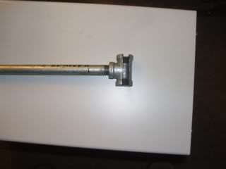
Link Plate Spring Removal Tool
luckyketch and bliz340--Here is a spring removal and
installer tool I made form 12"piece of 1/2" water pipe and a
T connector wit a slot cut in it. I would like say it was my
idea but I have to give the credit to bliz340.
http://i39.photobucket.com/albums/e156/luckyketch/Spring%20Removal%20Tool/DSCF2849.jpg
Tackle--You mean I don't have to hurt my hands doing
this? I guess now you are going to tell me you have
some easy way to avoid pinching your fingers when you
replace the metal slider on the skis (ouch).
I thought half the fun was showing all the bruises and cuts
to your kids. "wow nice bobo Dad"
luckyketch--I know this is cheating and there is probably a better way, but I bend them just a little in a vise. When you tighten them down you will never know it. Still get my fingers once in awhile but it doesn't seem to hurt quite as much.
NGK CHAMPION BOSCH Xref
luckyketch--Here is a real good cross reference for plugs. Reference By Heat Range
info available from Bombardier Museum, Manuals etc
westbranch--just got these 2 replies re info on my 1972
Oly...
I've transferred your request to Guy Pépin the Museum
Conservateur-restaurateur who will answer the production
part of your request.
"Further to your request for technical publications for your
Ski-Doo® Snowmobile Olympique 399cc 1972, the Museum have
a copy of the Parts Catalog (36$), Shop Manual (36$),
Owner's manual (7$) and the Sale Brochure of the 1972 all
models (5$) at a total cost of 84$. All fees cover
reproduction costs, postage, handling and taxes. If that
interests you, we will forward you a copy of the technical
publication requested.
Engine Compression Tables
kingdavid--Anyone know a good source for compression level charts for 69-73 doos? Specifically 299, 318, 335 singles and 340, 399 and 440 twins. Thanks.
Jimbo Jessup--
Singles (I don't have the numbers for the 318)
1970
299- 6.5:1
335- 7.5:1
1971
299- 7:1
335- 8:1
1972
299- 7:1
335- 9:1
1973- No changes
Twins
1970
399- 8.75:1
399(TNT)- 10:1
1971
399- 8.75:1
440(TNT)- 10.5:1
1972
399- 9:1
340(TNT)- 11.8:1
440(Nordic)- 9:1
440(TNT)- 11.8:1
1973
340(Olypique)- 9:1
399- 10:1
440(Olypique)- 10:1
440(TNT)- 10.5:1
gspaulding--Hello! Just a few added notes. If your altering compression ratio along with any exhaust port timing changes, these compression values are calculated as full stroke ratios not effective ratios. Just wanted to mention that.
kingdavid--Great info! Thanks. I just picked up a compression tester and I have been testing all of my engines.......that turn over. I am getting readings around 150 psi on all my one lungers. Is that pretty standard and within effective specs? I have one 400 with one cylinder at 150 and the other at 140....any concerns? Thanks again.
lowtekrednek--Greg, I would love that info- I think a lot of other guys would too. if you email it to me I will post it- I think I can make it permanent
gspaulding--Hello! I think I can fit it in right here.Basically compression ratio is how many times the trapped cylinder and head volume at top dead center, will go into the cylinder and head volume at bottom dead center. This is full stroke ratio and will be much higher than effective ratio because the entire cylinder volume (engine stroke) is being used for the ratio calculation.
But a 2 stroke doesn't start compressing mixture until the piston closes the exhaust port, and changing exhaust port timing (raising, lowering) can have a big effect on performance and of course compression ratio. So if you raised your exhaust port 1mm, true (effective) compression ratio has changed but using the full stroke calculation (like a 4stroke) you will always show the same compression ratio.
So in the calculation, stroke (full stroke) should be used for a 4 stroke, and port height which is the distance from top of cylinder to top of exhaust port opening should be used (effective).
So the ratio calculation is pie (3.1416) times bore, times bore, times stroke, (full stroke) or times port height, (effective) divided by 4, divided by the combustion chamber volume at TDC not counting the plug threads equals ratio. (Move the decimal point to the left 3 places)
Example would be an engine with a 66.5mm bore, and a 63mm stroke, with an exhaust port height of 30mm and a combustion chamber volume of 17cc. using the calculation, this configuration would have full stroke compression ratio of 12.87-1 regardless of any exhaust port timing changes whereas the effective ratio would be 6.13-1 and would change with port timing changes.
The combustion chamber volume needs to be known of course and I can go over that also if anybody wants to know. But I think I've used up enough space for now.
Thanks!
Greg
luckyketch--Greg, I would be very interested in how to
figure figure out the combustion area volume. We used to
fill fill the head chamber with liquid (water), after
removing it of course, and approximate the volume that
way, but I am sure there must be a more accurate way.
I found this site and his method is exactly the way we used
to do it when working on race engines. Did not know about
the food coloring or the alcohol then. Wish I would have.
Here is the site:
http://www.merkurxr4ti.com/chambervolume.html
Tony
luckyketch--Not a problem. You can also find the squish
area of a domed or stepped piston by using the same method
only slightly modified.
Drop the piston down exactly 1" or 2.54cm from top dead
center. Calculate the cc's at this distance. Then fill with
liquid and and measure the amount of liquid required to fill
cylinder up to plexiglass plate. Subtract this from the cc's
calculated in previous step and you now have the volume
filled by any irregular shaped piston, measure the thickness
of a previously install gasket and calculate the volume this
takes up. You now have all the info required in Gregs
formulas.
The idea was to find out what the difference between all
cylinders was. I can't remember for sure but I think was 1
to 1.5 % was acceptable.
This should all be calculated prior to final assembly cause
it could get a little messy.
gspaulding--Hello! Here's how I have always found
combustion chamber installed volume to use with the
compression ratio calculation. You'll need a cc buret
which is an accurate liquid measuring device, dial
indicator for finding TDC, measuring liquid for the buret,
and a little grease.
A 50/50 mix of marvel mystery oil and parts washing solvent
or gas works well for the liquid. It shouldn't be too thick
or the liquid clinging to the sides of the buret after
filling the combustion chamber can give you an inaccurate
reading of volume.
First remove the cylinder head, wipe a thin film of grease
around the upper area of the cylinder bore. Rotate the
piston to TDC, then wipe any excess grease from around the
piston. This grease seals the ring end gap so your
volume remains stable. Install the dial indicator and get
exactly TDC. Lock the crankshaft/flywheel etc. in place
somehow so the piston stays at TDC.
Install the cylinder with gaskets if any, and torque
correctly. Use the buret to fill the combustion chamber with
liquid up to the bottom of the spark plug threads.
Let the buret settle for a few minutes, read the volume used
from the buret, and you have your combustion chamber volume
needed for the compression ratio calculation.
Filling the combustion chamber to the bottom threads is
fairy accurate, but to be dead on you need to measure the
actual volume the plug displaces and then fill the liquid to
the top of the plug threads and subtract the value the plug
displaces. That's another process called flat plate
cylinder head volume measurement. But the process above will
be very close.
Thanks! Greg
luckyketch--1971 TNT 640 10:1 and 1970 Nordic Alpine 9:1
1970TNT--FYI Compression Ratio Compression (psi)
Range (psi)
6.5 96-114 18
6.6 98-116 18
6.7 100-119 19
6.8 102-121 19
6.9 104-124 20
7.0 106-126 20
7.1 107-129 22
7.2 109-131 22
7.3 111-134 23
7.4 113-136 23
7.5 115-139 24
7.6 117-142 25
7.7 119-144 25
7.8 121-147 26
7.9 123-149 26
8.0 125-152 27
SO YOURS IS 8:1 SO YOU SHOULD HAVE ABOUT 127 TO 154 IBS ON
YOUR COMPRESSION TESTER OR WHAT I DOO IS TO MULTIPLY THE 8
NUMBER BY 14.7 AND ADD 20 IT WILL GET YOU CLOSE
1970-1973 blizzard numbers
decoy706--Bones, lost my Blizzard numbers could you either send them or post some for me.
bones--Hi decoy706. Here is what I have for F/A Blizzard
#s.
1970s
7051 - 292, 292 units
7053 - 340, 308 units
7055 - 250, 20 units
7060 - 440, 311 units
7062 - 640, 290 units
7064 - 776, 354 units
1971s : For `71 there is two model series, 7100 - 7109 which
are cleated track, & series 7150- 7159. I only have one set
of prod #s & doo not know which series they are, I really
suspect the 7100 - 7109
250, 198 units
292, 262 units
336, 234 units
397, 113 units
437, 280 units
645, 245 units
797, 251 units
1972s
2501 - 300, 339 units
2502 - 340, 349 units
2503 - 395, 101 units
2504 - 438, 346 units
2505 - 645, 349 units
2506 - 797, 251 units
1973s
3501 - 298, 150 units
3509 - 345, 150 units
3503 - 441, 107 units
3504 - 645, 93 units
3505 - 797, 62 units
The model #s for `73 are the "GR" model #s & I really
question if there was that many GRs built I really
wonder if those prod # are for the winter sleds model #s
3521 - 3525
Bones
blizzard (and others) slide
instructions
torque reaction suspension sleds from ~ mid `70s
to ~ mid `80s
rv340--Hello All, I asked this before, but I need more help. Can one of you tell me how to change the slides on my 1981 Blizzard 5500. I know you have to drop the suspension but I really don't even know how to start. Any help would be appreciated. I hope to start on this tomorrow......Thanks
bones--Howdy rv340. The removal & installation of that
type of suspension has been a real nightmare for some
But.....Please follow this method (do not varry it) & you
will find it very, very easy to remove / install your
suspension.
You will need to remove just 2 bolts on each side, the ones
in the front & rear arms, you will not need to remove the
center idler shaft.
First, fully loosen of track tension. Next, make sure you
can loosen each bolt. Often you loosen one side, then go to
other side, the cross shafts turns & will not loosen the
bolt. You may need to loosen one side, back it out 1/2way,
oil the threads, then thread it back in, snug it up, then go
to other side & loosen bolt, go back to first side & loosen
bolt by "snapping" it. A air wrench is a big help, but not
required. Once you get the 4 bolts loose...
Tip sled on its side. Loosen the bolt in the limiter strap,
leave on by a couple of threads. Remove the cotter pin from
the pin in the top of the rear shock. postion sled back to
track on floor. Set the load spring tension to lowest
position on all 4 springs. Continue to fully remove the nut
from limiter strap bolt & remove bolt. Pull strap off the
lower shaft, leave strap hang on upper arm. Lay across rear
of seat & push down on rear of sled, reach under sled &
remove the pin from the rear shock. Lift up on rear of sled,
suspension arms will stand up with no spring tension. Block
rear of sled apx 1 ft higher than normal, to have rear arms
straight up but not lifting track. Remove the bolts from
either side of rear arm, push arm forward to make it fall
down Lift rear of sled apx 2 ft higher than normal. Remove
bolts from front arm, push arm forward to make it fall down.
Pull suspension from under sled.
Change the slides......
Slide suspension under sled. With rear up apx 2 ft, swing
the front arm up into position & install bolts, not tight.
When you swing the arm up, ensure you have the springs in
position, with the arm up, there will be No pre - load on
spring at this time. Lower rear of sled, you will likely
need to push down & forward some what as this pre loads the
front spring a little. With rear of sled up apx 1 ft, raise
rear arm into position, again make sure the springs are in
place. Install the two bolts, not tight. Push down & forward
on sled to load springs. Lay across the seat, reach under
sled & insert the pin into the top of rear shock. Thread
limiter strap back to normal. Install the bolt in limiter &
start nut on. Tip sled on side. Tighten limiter strap bolt.
Install cotter pin in shock pin. Tighten cross shaft bolts.
Set spring ride adjustment to desired. Tighten track.
If you under stand the above procedure & follow it
correctly, you really should have no trouble. Many guys want
to leave the spring not in position when the install the
bolts in the arms, then try to "FIGHT" the spring into
position after, don`t doo that, it just makes it harder
I can usually install one of them suspension into a sled by
my self in about 15 minutes, with no choice words, not
skinned knuckles etc
Good luck. Bones
P.S. Fellas, this method works for "all" the torque reaction
suspension sleds. From ~ mid `70s to ~ mid `80s
Canadian RV--I can personally vouch for Bones' method, he typed it up for me last yr...I followed it to a "T" and it worked no problem...
lshobie--same for the 300SS I suspect? thanks. Louis
bones--NO.....The Elan SS has a 2nd version of the ground
leveler & is different from the torque reaction suspension.
For the ground leveler you leave it all together in the
suspension frame & install it, then install the rear link
plates. Bones